
Table of Contents
Table of Contents
The Fundamental Principle of Engine Power
The single biggest factor that determines an engine’s ultimate power potential is the total inlet valve area. Not all cylinder head designs have the same flow efficiency for a given valve area though and it is the flow potential rather than the valve area itself that really determines the power potential but valve area is much easier to measure and provides an ideal starting point for further analysis. There is no point however in having big valves if the port shape or other factors restrict the flow. To discuss this further it is best to consider engines with 2 valves per cylinder separately from 4 valve valve engines (or even 5 valve engines which are gradually appearing in road cars).
2 Valve Per Cylinder Engines
Engines with only one inlet and one exhaust valve can be further split into two main categories.
Parallel Valve Engines
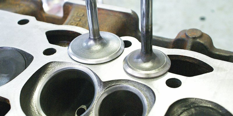
In this type of design the valve stems are parallel to each other and usually, but not always, parallel to the cylinder bore axis. Examples might be the Mini, MGB, VW Golf, Peugeot 205 and Ford Crossflow engines. The total valve diameter is directly limited by the bore size because the valves open into the bore.
There obviously needs to be some clearance between the two valves and also between each valve and the adjacent bore wall simply to prevent contact. Production engines might have 3mm or 4mm for each of these clearances although this can be reduced on a race engine to around 1.5mm between the valves and 1mm to 1.5 mm between each valve and the bore wall to allow the largest possible valves to be fitted. So at best there is a limit on total valve diameter of about 3.5mm to 4.5mm less than the bore diameter.
This remaining space would normally be allocated as about 55% to 57% for the inlet valve and 43% to 45% for the exhaust valve diameter. In other words the exhaust valve would be around 80% of the diameter of the inlet valve for best power output – perhaps even a little less in some cases.
Combustion chambers can either be of the “bathtub” type where the volume is contained mainly in the cylinder head or the “Heron” design where the head face is flat and the volume is in the piston dish and between the top of the piston and the top of the bore.
Regardless of the exact design chosen there is always going to be some loss of flow potential because of shrouding between the valves and the closely adjacent bore wall or combustion chamber walls. In simple terms there is just not enough space for the airflow to get past the valve head into the cylinder cleanly. The bigger the valves and the closer they end up to an adjacent wall the greater the shrouding effect becomes and a law of diminishing returns sets in.
In some cases a smaller valve ends up producing more flow than a larger one if the required clearance space around the valve head can’t be achieved. The effect of shrouding can be to reduce the flow and power potential by around 10% compared to the same sizes valves with zero shrouding.
Early designs of this type of engine had pushrod type valve trains and the Mini and MGB engines were limited even further by their Siamese port design. Some of the more modern single overhead cam engines can rival the inclined valve type design in their power output though. A little common sense needs to be applied when evaluating these types of engine.
Inclined Valve Engines
In these designs the valves are angled both relative to each other and to the bore axis. Examples include the Ford CVH and Twin Cam engines which have large angles between the valves and the Ford Pinto engine which has a fairly small included angle. This design has two main advantages. Because the valves open away from the bore wall in towards the centre of the cylinder there is little or no shrouding of the flow.
As the valve opens further and the airflow increases, so the necessary space around the valve head increases at the same time. Secondly it enables larger valves to be fitted in a given bore diameter than the parallel valve head design. Within limits, the greater the angle between the valves the larger they can become although if the included angle is too large the inlet valve can hit the exhaust valve when they are both open during the overlap period.
Disadvantages of this design is that the combustion chamber has to be something like a hemisphere, or at least fairly domed, and this shape isn’t very compact and doesn’t burn well. The advantages of extra valve area and lack of shrouding outweigh this consideration by a large margin though.
4 Valve Per Cylinder Engines
The constraints of fitting 4 valves and their related valve trains into a cylinder head means that all 4 valve designs end up being fairly similar – at least in flow terms. The inlet valves are angled away from the exhaust valves, the spark plug ends up central in the chamber and usually twin overhead cams are used – although a few designs manage with a single cam and rockers. There is little or no shrouding with most 4 valve engines and in effect they are like multi valve versions of the inclined design of 2 valve engine.
There is a significant difference though between 4 valve and 2 valve engines in terms of flow and power potential for a given total valve area. This is because the ratio of total valve area to total valve circumference is not the same. To understand this better let’s look at an example. Copyright David Baker and Puma Race Engines
Compare an engine with two small inlet valves of 25mm diameter with a similar sized engine with one large valve of 35.36mm diameter. The total valve area is the same in both cases – about 982 square mm. So the total peak flow when the valves are fully open should be very similar. The total circumference is very different though. The two small valves have a total circumference of 157mm.
The single large valve has a circumference of only 111mm. The ratio is 1.41 to 1 – or in other words the square root of 2. This has a big effect on flow at low valve lifts. If all three valves are open by the same small amount – say 1mm – the two small valves have a flow area which is 41% bigger and consequently flow more air. As the valves open fully and the valve area becomes the limiting factor, this effect diminishes and ultimately disappears.
The effect of this improved low lift flow is to give the two small inlet valves a power advantage over a single valve of the same area. The effect depends on the cam profile used on each engine but is in the region of 10% to 15%.
Advanced Valve Configurations: 5 Valve and Beyond
The Evolution to 5 Valve Technology

While 4 valve designs have dominated modern engine architecture for decades, some manufacturers have experimented with 5 valve configurations to further optimize airflow characteristics. The typical 5 valve arrangement features three inlet valves and two exhaust valves per cylinder, allowing for even greater total inlet valve area while maintaining adequate exhaust flow capacity.
Benefits of 5 Valve Designs
The primary advantage of 5 valve configurations lies in the increased total circumference of the inlet valves, which further enhances low-lift flow characteristics compared to 4 valve designs. This arrangement allows for more precise control of airflow at different engine speeds and loads, potentially improving both power output and fuel efficiency across a broader RPM range.
Challenges and Limitations
However, 5 valve designs introduce significant complexity in valve train arrangements, requiring more sophisticated camshaft profiles and timing mechanisms. The additional hardware increases manufacturing costs and maintenance requirements, which explains why these configurations remain relatively uncommon in production engines.
Valve Train Design Considerations
Pushrod vs. Overhead Cam Systems
The choice of valve actuation system significantly impacts valve sizing possibilities and overall engine performance. Pushrod systems, while simpler and more compact, often limit valve sizes due to their indirect actuation method and the need for rocker arm clearance. Overhead cam systems, particularly twin cam arrangements, allow for more direct valve control and typically enable larger valve diameters.
Single Overhead Cam (SOHC) Compromises
Single overhead cam designs attempt to balance complexity with performance by using rocker arms or followers to operate both inlet and exhaust valves from a single camshaft. While this reduces mechanical complexity compared to twin cam systems, it often requires compromises in valve timing and sizing that can limit ultimate power potential.
Twin Overhead Cam (DOHC) Advantages
Twin overhead cam configurations provide the most flexibility in valve timing and sizing, allowing independent optimization of inlet and exhaust valve events. This design freedom enables engineers to maximize valve area while maintaining optimal timing characteristics for different engine operating conditions.
Combustion Chamber Design Impact
Hemispherical Chamber Characteristics
Hemispherical combustion chambers, commonly used with inclined valve designs, provide excellent airflow characteristics but present challenges for combustion efficiency. The large surface area relative to volume can increase heat losses and create flame travel distances that may not be optimal for all operating conditions.
Pentroof Chamber Design
Modern 4 valve engines often employ pentroof combustion chamber designs that attempt to balance the airflow advantages of angled valves with improved combustion characteristics. These chambers typically feature a more compact shape than full hemispheres while maintaining good valve shrouding characteristics.
Wedge Chamber Considerations
Wedge-shaped combustion chambers, often found in parallel valve engines, can provide good combustion characteristics due to their compact shape and controlled flame propagation paths. However, they may limit valve sizes and create shrouding issues that reduce maximum airflow potential.
Flow Coefficient and Port Design
Understanding Flow Coefficients
The relationship between valve area and actual airflow is quantified through flow coefficients, which measure how efficiently a valve and port combination moves air compared to a theoretical perfect orifice of the same area. Typical automotive valves achieve flow coefficients between 0.3 and 0.6, depending on design quality and operating conditions.
Port Shape Optimization
Even with optimal valve sizing, poor port design can severely limit airflow potential. Modern computational fluid dynamics (CFD) analysis allows engineers to optimize port shapes for maximum flow efficiency, reducing turbulence and pressure losses that can negate the benefits of larger valves.
Velocity Considerations
While larger valves generally allow greater total airflow, they can also reduce air velocity at low engine speeds, potentially affecting fuel atomization and combustion quality. Engine designers must balance maximum flow potential with maintaining adequate air velocity across the entire operating range.
Manufacturing and Tolerance Considerations
Production Valve Sizing Limitations
Mass production requirements often prevent engines from achieving theoretical maximum valve sizes due to manufacturing tolerances and assembly considerations. Production engines typically maintain larger clearances than would be optimal for maximum performance to ensure reliable assembly and operation across varying manufacturing conditions.
Race Engine Optimization
Race engines can utilize much tighter tolerances and clearances, allowing valve sizes to approach theoretical maximums. Hand-assembly techniques and premium materials enable clearances that would be impractical for mass production, often yielding significant performance improvements.
Quality Control Impact
Variations in manufacturing quality can significantly affect the relationship between valve area and actual flow performance. Seat concentricity, valve guide wear, and port surface finish all influence flow characteristics, making quality control critical for achieving design objectives.
Valve Timing and Duration Effects
Overlap Period Optimization
The period when both inlet and exhaust valves are open simultaneously (overlap) significantly affects engine performance characteristics. Proper valve sizing must consider not just maximum flow potential but also how valves interact during overlap periods, particularly in high-performance applications.
Variable Valve Timing Integration
Modern variable valve timing systems allow optimization of valve events for different operating conditions, potentially changing the optimal valve sizing equations. These systems can compensate for some valve sizing compromises by adjusting timing to maximize airflow when needed most.
Duration vs. Lift Considerations
The relationship between valve lift and duration affects how valve area translates to actual airflow. Longer duration profiles can partially compensate for smaller valve areas, while higher lift profiles can maximize the benefit of larger valves within packaging constraints.
Material and Weight Considerations
Valve Weight Impact on RPM Capability
Larger valves inherently weigh more than smaller ones, potentially limiting maximum engine RPM due to valve train dynamics. This consideration becomes particularly important in high-performance applications where engine speed capabilities directly affect power potential.
Advanced Materials Applications
Modern materials such as titanium and hollow-stem valves allow larger valve diameters without proportional weight increases, enabling designers to optimize valve area without compromising high-RPM operation. However, these materials significantly increase manufacturing costs.
Thermal Considerations
Larger valves can provide better heat dissipation paths, particularly for exhaust valves that operate in extremely high-temperature environments. This thermal advantage can enable more aggressive tuning and higher specific power outputs in some applications.
Future Trends in Valve Technology
Electromagnetic Valve Actuation
Emerging electromagnetic valve actuation systems eliminate traditional mechanical constraints, potentially allowing completely new approaches to valve sizing and timing optimization. These systems could enable variable valve lift and duration that adapts continuously to operating conditions.
Pneumatic Systems
Some racing applications already employ pneumatic valve actuation to achieve higher RPM capabilities with larger valves. While currently limited to specialized applications, these technologies may eventually influence production engine design.
Integration with Forced Induction
The increasing prevalence of turbocharging and supercharging systems affects optimal valve sizing equations, as boost pressure can partially compensate for smaller valve areas. Future engine designs will likely optimize valve configurations specifically for forced induction applications.
Practical Applications and Tuning Implications
Aftermarket Valve Upgrades
Understanding valve area relationships helps tuners evaluate the potential benefits of aftermarket valve upgrades. Simply installing larger valves without considering shrouding effects and port modifications may not yield expected performance improvements.
Head Porting Considerations
Cylinder head porting work must be coordinated with valve sizing to achieve optimal results. Enlarging ports without appropriate valve upgrades, or installing larger valves in unmodified ports, can create mismatched combinations that limit performance gains.
Compression Ratio Interactions
Valve sizing changes can affect optimal compression ratios, particularly when combustion chamber shapes must be modified to accommodate larger valves. These interactions require careful consideration during engine modification planning.
Conclusion: Optimizing Valve Design for Maximum Performance
Achieving optimal engine performance requires careful consideration of all valve design parameters, from basic area calculations to complex interactions between valve sizing, combustion chamber design, and valve train dynamics. While larger valves generally provide greater power potential, the relationship is not linear, and multiple factors must be balanced to achieve the best overall results.
Modern engine design increasingly relies on sophisticated analysis tools and advanced materials to push valve designs toward theoretical limits while maintaining reliability and manufacturability. Understanding these relationships enables both engine designers and tuners to make informed decisions that maximize performance within practical constraints.
The evolution toward more complex valve configurations, combined with emerging technologies like variable valve actuation and advanced materials, suggests that valve design will continue to be a critical factor in engine performance optimization for the foreseeable future. Success in this area requires not just theoretical understanding but also practical experience with the many compromises and interactions that determine real-world performance outcomes.